Double Wishbone Suspensions
On my older PSU personal website I had a short essay I had written about the elements that make up a Double Wishbone Suspension system. It somehow has ended up on the first page of google search results when searching for "double wishbone suspension". So I figured that I should bring it over to this newer version of my website.
The Purpose of Suspension in Automobiles:
There are two main problems that would occur if suspension systems were not used in cars. If a car did not have a suspension system then it is assumed that the car has a rigid beam to connect the chassis to the wheel mount. This rigid connection would result in the bumps on the road being transmitted directly into the chassis of the car since there is no "bounce" from the springs that would be found in a normal suspension. This rigid non-spring connection would make for a very uncomfortable ride for the occupants of the vehicle.
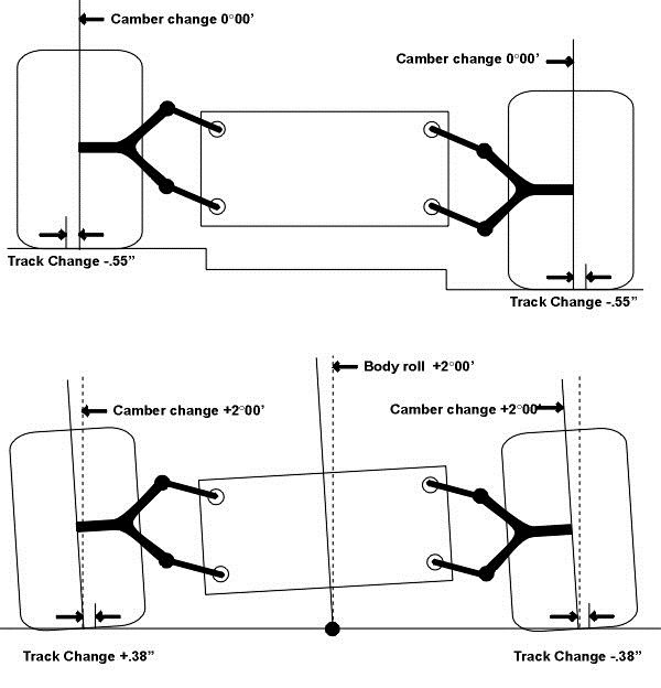
The other main problem is that a rigid system deals poorly with body roll. Body roll occurs in the case of the car turning or if one side of the car hits a bump and the other side does not. In contrast to a rigid design the image below shows how well a double wishbone suspension system deals with body roll. The bottom of the tires remain parallel to the ground despite the fact that one tire is sitting higher than the other tire. This happens due to the non-rigidness and the geometry of the double wishbone design. In addition the car body levels out and the body roll is gone. Click on the image to view the source of the image. This source page includes more images of the suspension dealing with bumps and rolls

Image from: Autozine Technical School
In the case of a rigid connection the tires are only parallel to the ground whenever the body of the car has no roll. When the body of the car rolls the rigid connection to the wheel mounts does not allow for all the tires to remain level to the ground. The bottoms of the two tires shown need to connect to form a straight line at all times due to the rigidity of the system. It can be seen that the bottoms of the two tires would need to be angled in such a way that both tires are not parallel to the ground nor touching the ground at the same time. When a tire is not parallel to the ground the tire can have reduced grip. Especially when a tire is completely off of the ground disastrous results may occur. Reduced grip prevents the driver from being able to turn, brake, or accelerate effectively.
The Overall Function:
The parts of the suspension mentioned in this paragraph will be explained in the third section in more detail.
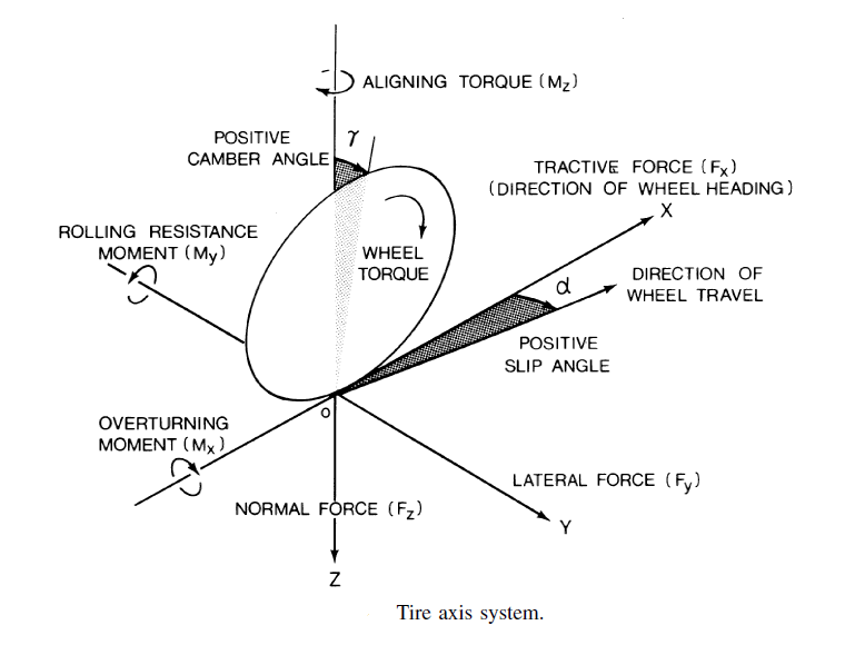
As the wheels rotate with respect to the Y axis (My rotation) the wheels pull the car in the forward direction (positive X direction) and as the wheels turn (Mz rotation) the car is pulled in the lateral direction (Y direction). These forces are carried through the rigid wishbone arms and into the chassis through the thrust bearings. The thrust bearings also allow free rotation around the X axis (Mx rotation) which allows the chassis to move up and down (Z direction) relative to the wheel mount. This is what allows the bottom of the wheels to stay flat to the ground plane as seen back in the first image on this page. Ball joint bearings allow the wheel mount to be steered by the steering arm.
The spring does the important job of carrying the vertical load (Z direction) of the car and the damper dissipates energy from the spring so that the spring will come to rest quicker. A quick overview of how the spring and damper works will be in the fourth section of this page.

Image from: Mechanics of Pneumatic Tires - Page 8
The Principal Mechanical Elements:
1. The larger circular hole to the right side is the location for the wheel to be mounted. This uses a cylindrical thrust bearing that allows the wheel to rotate about the Y axis. Bearings in general use lubricated or roller surfaces combined with certain geometries designed to allow movements or rotations in certain directions and restrict movement or rotations in other directions.
2. The wishbones (simple rigid beams) are connected to the wheel mount with ball joint bearings. The ball joint bearings allow limited rotation about all three axes. This allows the wheels of the car to turn when given steering input.
3. The chassis of the car is connected to the suspension system at the four points at the ends of the two wishbones. This connection uses cylindrical thrust bearings to allow rotation about the X axis only.
4. The smaller arm that is connected to the wheel mount is the steering arm. This connects to the steering system of the car and is used to rotate the wheel mount about the Z axis which then steers the wheels.
The spring (red) and the damper (black cylinder underneath the red spring) are combined into one compact unit. These two elements are neither bearings nor rigid beams and can only be examined using a dynamic model of a spring-mass-damper system which is explained in the next section.
Image from: Car Bibles - Suspension Bible
The Spring - Mass - Damper system:
Rigid members are simple to model. If one end of a rigid beam is pushed one meter forward from the position at which it started then the other end of the beam will also be displaced one meter forward from where that end of the beam started. Springs on the other hand behave differently as their displacement can oscillate. If one end of a spring is moved slowly then the spring will behave like a rigid beam and the other end of the spring will displace by an equal amount. However if the input force begins to oscillate at a higher frequency then the spring begins to behave differently than the rigid beam. More information about this phenomenon can be found by researching vibrational transmissibility.
The damper is a mechanical element that always opposes the movement of the mass. The damper works by using internal viscous forces to dissipate energy from the system depending on how fast the mass is moving. An ideal spring would oscillate back and forth forever if there was no damping in the system. No such ideal spring exists in the real world since all springs have some internal damping, but this internal damping is not enough for many automotive applications.
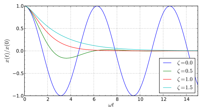
The blue line in the following image shows the oscillation of a spring with no damping. This would be undesirable in a car because the car would never stop oscillating after hitting a single bump. The green line more accurately depicts the behavior of a car's suspension system. This green line shows some oscillation but then quickly reaches a steady state value at zero displacement.

Image from: Wikipedia - Harmonic Oscillator